Open your Pod and get root access
Start here if you have a stock Pod and have never opened a shell on it. Root is the administrator account on the Pod’s Linux computer. You first reach it over a temporary USB-to-serial connection; after installing sleepypod, you can use SSH over Wi-Fi and put the case back together.
This procedure builds on free-sleep’s installation guide and sleepypod’s own Pod 5 hardware photos. You do not need to install free-sleep first. If you already have a working root shell, skip to install Core.
1. Identify your hardware
| Hardware | Start here |
|---|---|
| Pod 3 with an SD card | Use the separate SD-card root-access procedure . Back up the card before modifying it. The UART boot commands below are not an SD-card guide. |
| Pod 3 without an SD card | Follow the serial procedure below, using the Pod 3 opening photos . |
| Pod 4 | Follow the serial procedure with the Pod 4 opening notes below. |
| Pod 5 | Complete initial setup in the Eight Sleep app first, as required by the current free-sleep guide, then follow the serial procedure. |
| Pod 1 or 2 | Not covered by this guide. |
Board revisions and firmware differ. Match the board markings and connector location to the photos; stop if yours differs. The commands below cover the documented slot A boot path, not an arbitrary partition layout.
2. Gather the parts
- A Tag-Connect TC2070-IDC cable (the 14-pin model with retaining legs). Manufacturer’s product page .
- An FTDI FT232RL USB-to-TTL serial adapter capable of 921600 baud, with 3.3 V logic, and a USB cable for your computer. Example adapter on Amazon .
- Three suitable Dupont jumper wires for ground, transmit, and receive. Example jumper-wire kit on Amazon .
- A screwdriver/bit assortment that fits your case screws, and a plastic opening tool. Check the actual screw head; do not force a nearly fitting bit.
- A Mac or Linux computer with minicom installed. The commands here use those platforms.
This is a UART serial console through the Tag-Connect footprint, often called the “JTAG” procedure in community guides. The harness itself is passive; it is not a USB adapter or a JTAG programmer.
Disconnect mains power before opening the case or touching the wiring. Follow the Pod’s drain/disconnection instructions before moving it; keep water away from the exposed electronics. During the later powered serial session, leave the assembly supported and do not touch the boards or power-supply area. Opening the enclosure and changing the boot process can damage the device if done incorrectly.
3. Open the enclosure
Pod 3 without an SD card
Use the numbered Pod 3 teardown photos : the sequence shows opening around the fan, removing screws, releasing the grille, and lifting the lid. Follow that model’s photos rather than applying the Pod 4/5 base-panel steps.
Pod 4
Remove the four screws hidden under the rubber feet. Support the hub while separating it from the bottom panel: the side panels can slide free. Slide each side panel down slightly, then out; release the front grille the same way. Note how its tabs engage the top and base before removal. See the illustrated Pod 4 teardown for the board location.
Pod 5
The sleepypod photos below show the four base screws exposed by removing the feet, the bottom cover lifted off, and the serial connector on control board 830-00067-00 REV-17. Remove the matching base fasteners and release the cover without pulling attached wiring. Retain the feet and screws for reassembly. A firsthand Pod 5 opening report describes sliding the side panels downward to release them after freeing the base; support the chassis as you expose the control board. Do not pull on the board or remove its modules to make room for the harness. The photos identify the observed board revision; they are not a guarantee that every Pod 5 enclosure is identical.
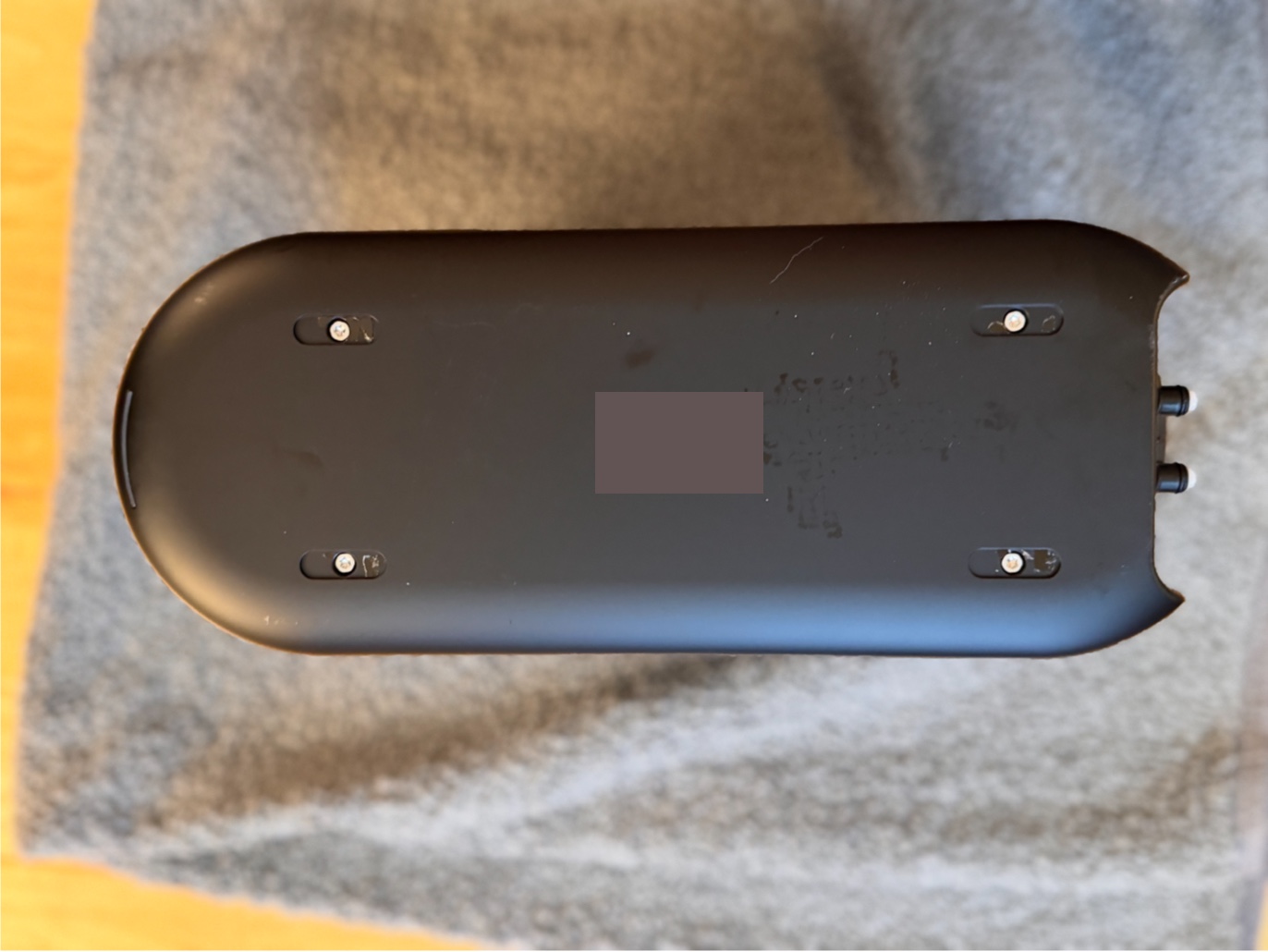
Pod 5: the four feet conceal the base screws. Original sleepypod hardware photo.
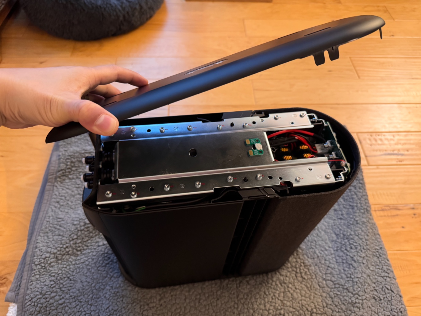
Bottom cover removed. Keep the chassis supported while accessing the control board.
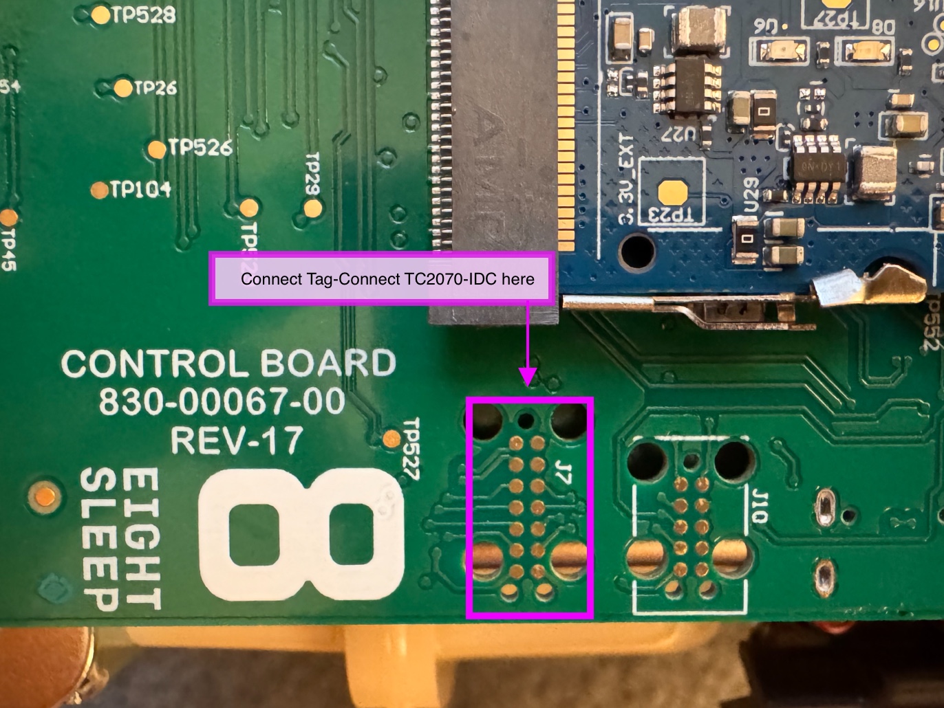
Use the marked J7 footprint on this board, not the nearby J10 footprint. Click to enlarge.
4. Wire the serial connection
With Pod power disconnected, set the adapter for 3.3 V and confirm its TX logic level from the adapter’s documentation. A voltage jumper on an arbitrary clone may only select its power-output voltage. Do not use a conventional RS-232 voltage-level adapter.
| Pod signal, in the referenced board pinout | USB serial adapter |
|---|---|
| Pin 1 — GND | GND |
| Pin 6 — RX (Pod receives) | TXD (adapter sends) |
| Pin 8 — TX (Pod sends) | RXD (adapter receives) |
| Power / VCC | Leave disconnected |
Use only those three signal wires. Power the Pod from its normal power supply later, not from the FTDI adapter. TX and RX cross between devices; wire colors are not pin identities.
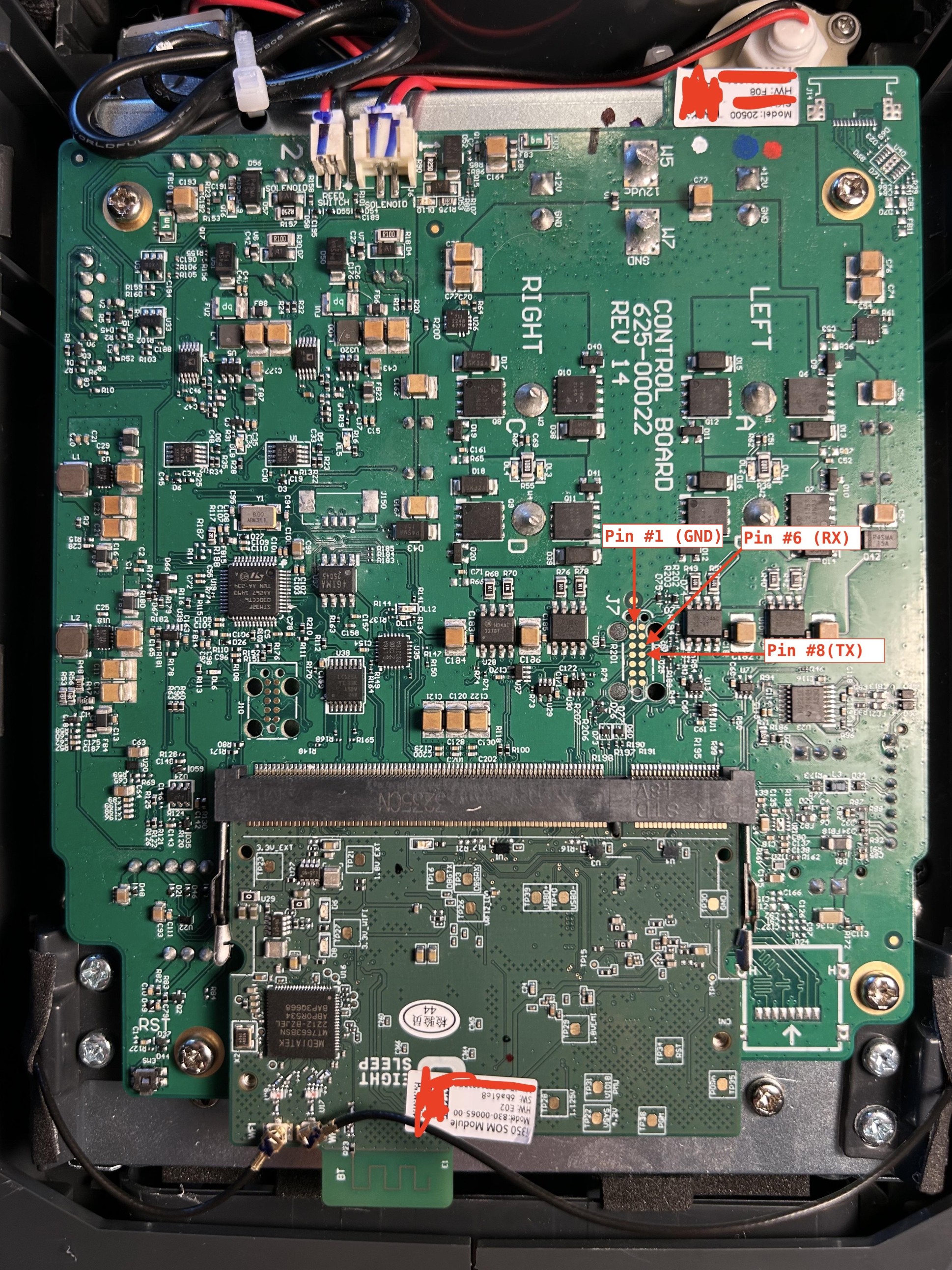
free-sleep’s annotated pinout on its pictured board revision. Check orientation against your own board.
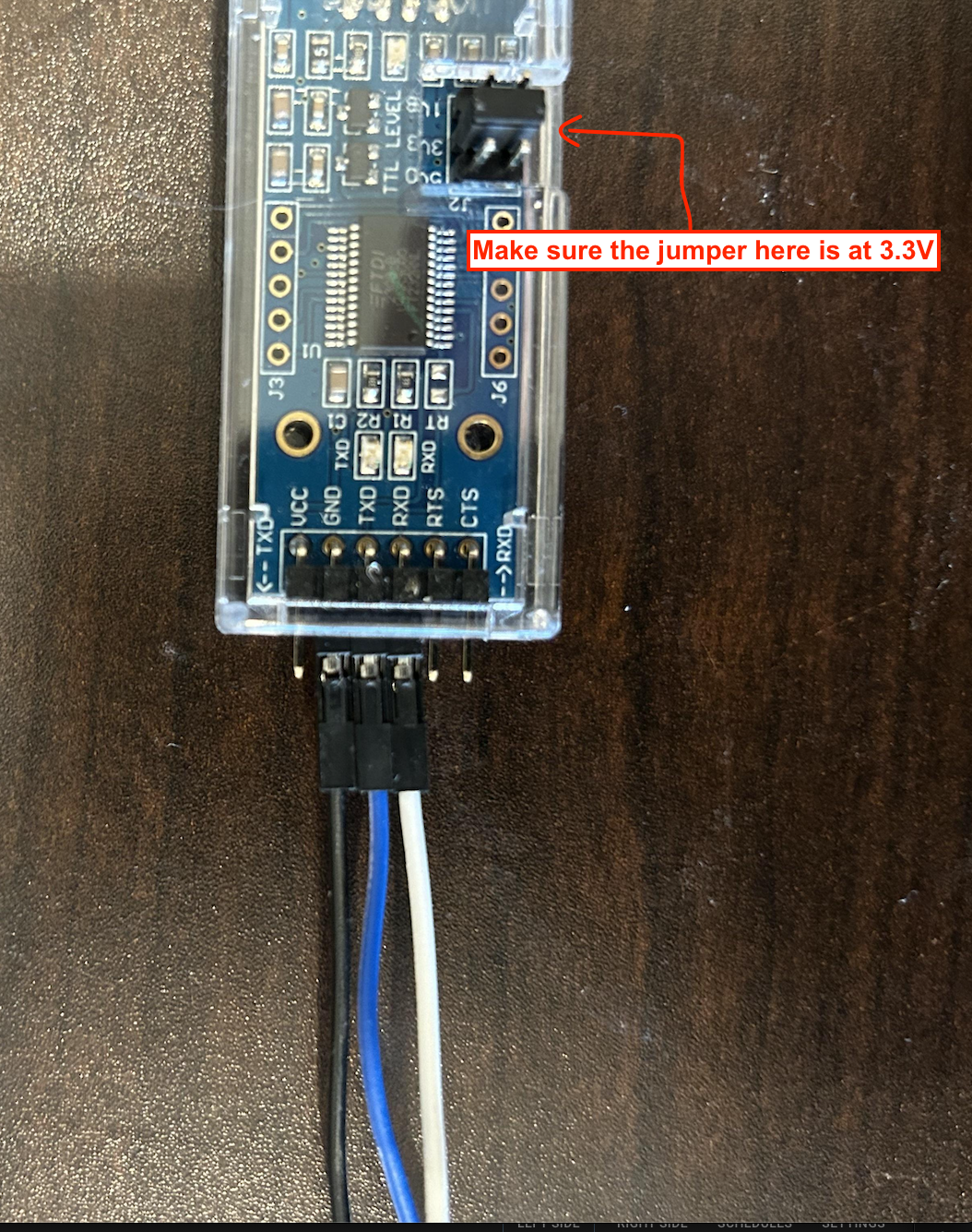
free-sleep’s adapter example: 3.3 V selected; VCC, RTS, and CTS are unused.
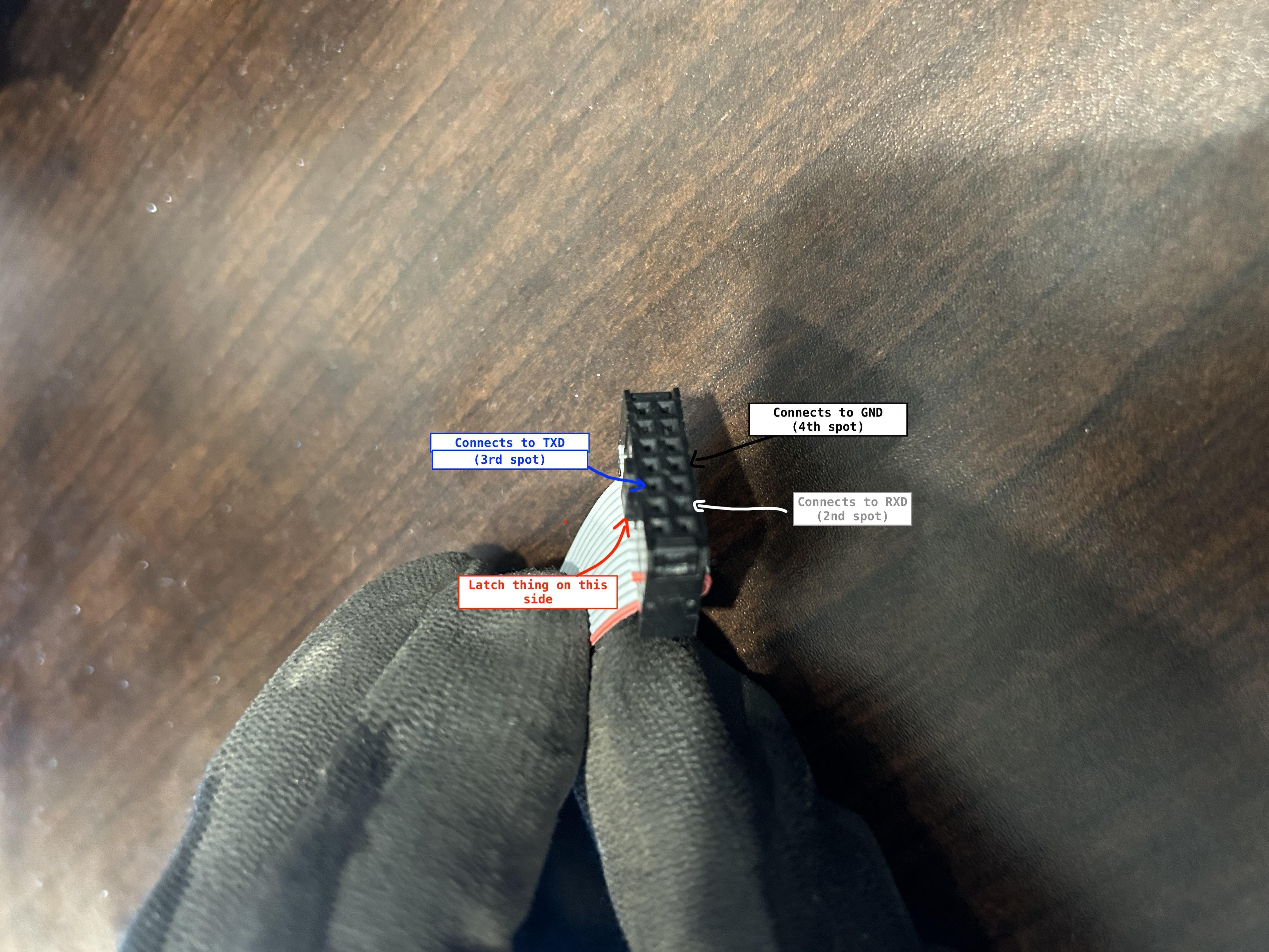
free-sleep’s cable-side view. Match the latch orientation before locating the three wire sockets.
Match the cable’s pin-1 marking and keyed orientation to the harness assembly photos . Do not count IDC socket positions from a mirrored view or assume its numbering from the board photo. Seat the Tag-Connect pins squarely and secure its retaining legs. Connect the adapter’s USB cable to the computer while leaving Pod power off.
5. Open the terminal on your computer
Install minicom using your computer’s package manager if needed:
# macOS, with Homebrew already installed
brew install minicom

# Debian / Ubuntu Linux
sudo apt install minicom
Find the serial device that appears when you plug in the adapter:
# macOS
ls /dev/cu.usbserial*

# Linux
ls /dev/ttyUSB*
Use the actual device name. For example, on your computer:
minicom -b 921600 -o -D /dev/cu.usbserial-B0010NHKOn Linux, substitute your device, such as /dev/ttyUSB0. Press Ctrl-A, then O to open minicom’s configuration menu and choose Serial port setup. Use 921600 baud, 8 data bits, no parity, 1 stop bit (8N1) and disable both hardware and software flow control. The three-wire connection has no RTS/CTS handshake.
Now connect the Pod’s normal power supply. Watch the boot messages and press a key when you see Hit any key to stop autoboot. A U-Boot prompt means the bootloader accepted the interruption. The following commands go into that prompt, not your computer’s shell.
6. Boot a temporary administrator shell
First inspect the active slot:
printenv current_slotContinue only if it reports current_slot=a. If it reports B, is missing, or the expected boot prompt never appears, stop and consult the upstream procedure and model-specific reset notes . Do not guess a partition name or factory-reset as a routine troubleshooting step; reset can change your configuration.
For the documented slot-A setup, enter:
setenv bootargs "root=PARTLABEL=rootfs_a rootwait init=/bin/bash"
run bootcmd
These commands start Linux with a shell instead of normal startup. Do not run saveenv: the modified boot arguments are for this boot, not a permanent boot configuration.
At the resulting Pod shell, mount the runtime filesystems and make the root filesystem writable:
mount -t proc proc /proc
mount -t sysfs sysfs /sys
mount -t devtmpfs devtmpfs /dev
mount -t tmpfs tmpfs /run
mount -o remount,rw /
Set passwords you will retain for the two existing accounts. Password entry does not display characters; enter each password twice when prompted:
passwd root
passwd rewt
sync
reboot -f
rewt is an account name, not a command or a tool. If an expected account or mount is absent, stop and capture the exact error; do not create replacement accounts or change partitions to make the commands fit.
7. Verify normal login and prevent firmware updates
Let the next boot complete without interrupting it. Log into the serial console as root, using the password you just set. Run:
id -uIt should print 0. You now have the root shell needed by the installer. A password set successfully in the temporary shell is not enough: verify it survives the normal boot.
Before bringing the Pod online, stop and mask the stock update services identified by the bootstrap instructions:
systemctl disable --now swupdate-progress swupdate swupdate.socket defibrillator eight-kernel
systemctl mask swupdate-progress swupdate swupdate.socket defibrillator eight-kernel
Some firmware revisions lack some of these units; distinguish “unit not found” from a failure to stop an installed unit. Keep a record of what was enabled before changing it. This opts out of the vendor’s automatic update path. The upstream free-sleep takeover also disables additional runtime services; do not apply its entire service list blindly to a sleepypod installation, which still needs the firmware hardware-control process.
8. Join Wi-Fi and install sleepypod
Check whether initial setup already connected the Pod:
nmcli device status
nmcli -g ip4.address device show wlan0
If wlan0 is disconnected, connect from the Pod’s serial console. --ask prompts for the password rather than embedding it in the command:
nmcli --ask device wifi connect "YOUR_WIFI_NAME" ifname wlan0
nmcli -g ip4.address device show wlan0
Use a network where your computer and Pod can reach each other. The initial installer needs internet access. Keep the serial session open and continue to Install Core, running its commands directly here as root. You do not need working SSH to perform this installation.
When the installer offers SSH setup, provide your computer’s public key (the .pub file), never its private key. If you do not already have a key, create a dedicated one in a terminal on your computer:
ssh-keygen -t ed25519 -f ~/.ssh/sleepypod_ed25519
cat ~/.ssh/sleepypod_ed25519.pub
Choose a passphrase when prompted. If that filename already exists, use the existing key or choose a new filename; do not overwrite it. Paste the full .pub line into the installer’s prompt. After setup, verify a new terminal on your computer can connect using that key:
ssh -i ~/.ssh/sleepypod_ed25519 -p 8822 root@POD_IPReplace POD_IP with the address printed by nmcli (without the /24 or other subnet suffix); if you used an existing key, substitute its path. Run id -u and sp-status in that new SSH session. Keep serial access until this works. A stock Pod’s root password alone does not enable root SSH; the installer configures key-only access. The dac service account is not an interactive login account.
9. Disconnect and reassemble
After SSH and the web interface work, shut the Pod down from its root shell with poweroff and disconnect mains power. Unplug the USB adapter and release the Tag-Connect harness without pulling on its wires. Refit the enclosure tabs, panels, screws, and feet; check for pinched wires before restoring normal connections and power.
Open http://POD_IP:3000 on the same network, confirm the timezone and selected side, and follow the installation verification steps. Temperature testing belongs after reassembly and reconnecting the cover.
If the console does not work
| Symptom | Check next |
|---|---|
| No serial device on the computer | USB data cable, adapter driver, and the device that appears when reconnecting USB. |
| Permission denied opening the port | Your computer’s serial-device permissions; on Linux this commonly requires membership in the serial-device group. |
| No boot text | Pod power, common ground, TX/RX crossing, harness seating, and the correct board footprint. Disconnect Pod power before changing wiring. |
| Garbled output | 921600 baud, 8N1, adapter capability, and stable contacts. |
| Text appears but keypresses do nothing | Adapter TXD to Pod RX, flow control disabled, and the boot interruption timing. |
| Root works on serial but SSH fails | Finish the installer’s SSH-key setup and use port 8822; verify the actual Pod IP. |
Sources and photo credits
- free-sleep installation guide , checked September 29, 2026, including the Pod 5 initial-setup prerequisite. Its pinned teardown and wiring assets are credited above; license retained in this site’s
licenses/directory. - sleepypod bootstrap and SSH notes and installer .
- NetworkManager Wi-Fi command reference for the interactive
--askconnection command. - Original Pod 5 hardware photos . Media revisions and checksums are recorded in
capture/manifest.json.